Building a Wall Box for Test D - E
To build a wall box to test for transmit/receive pair phasing, you need the following items:
|
•
|
Two 1N4001 diodes (NCR P/N 007-9812817) |
|
•
|
Two 47 cm (18 in.) patch cords |
Assemble the box in the following manner:
|
1.
|
Remove the cover of the wall box. |
|
2.
|
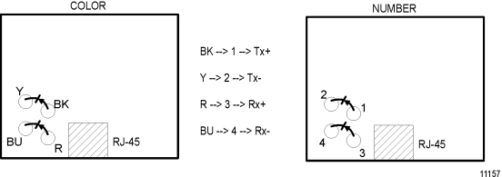
The PC board coding of the insulation displacement terminals is either by number or by color, as shown earlier in Figure 3-11. |
|
3.
|
Using the wire insertion tool, connect the anode of a diode to Bk (#1, Tx+) and the cathode to Y (#2, Tx-). |
|
4.
|
Connect the anode of the other diode to R (#3, Rx+) and the cathode to BU (#4, Rx-). Figure 3-20 shows the modified wall box. |
To use this box to test a particular line:
|
1.
|
Using a patch cord, connect the modified wall box to the workstation end wall box. |
|
2.
|
At the other end (See Figure 3-21) connect the second wall box directly to the RJ-45 terminated cable which plugs into the hub. |
Case D: Tests for transmit pair phasing
At the wall box at the hub end, with the positive meter probe on BK and the negative probe on the Y, the resistance should be low.
Case E: Tests for receive pair phasing
At the wall box at the hub end, with the positive meter probe on R and the negative probe on BU, the resistance should be low. Swap the wires BK to Y and Y to BK, and so forth, if a high resistance or open line is observed.
